Industry – Technical Math & Measurement

The world of the advanced technician is governed by the rigorous, unforgiving language of mathematics. While your conceptual understanding of a system is philosophical, the measurement of that system is absolutely empirical. The ability to correctly interpret a fraction, convert a dimension, or calculate an electrical value is not simply a clerical skill; it is an epistemic imperative, a non-negotiable condition for accessing truth within the physical world. In the mechatronic environment, all concepts, from motor speed to component fit, must be quantified by numbers. An error in calculation is not a small mistake; it is an untruth introduced into the production system, resulting in dimensional failure, machine instability, or a catastrophic equipment shutdown. To master technical math is to commit to the highest standard of empirical precision.
Metrology and the Philosophy of Tolerance
Metrology is simply the science of measurement. In Advanced Manufacturing, its most important concept is Tolerance. Tolerance defines exactly how much difference is allowed between the perfect blueprint size and the actual size of the manufactured part. When we design automated systems, we aim for perfect fit, but we accept that small variations are inevitable. However, if a part is outside its tolerance, the consequences are severe
- Metrology (The Science):
- This is the high-level discipline of ensuring measurement systems are accurate. In the factory, this means verifying that all measurement tools (calipers, micrometers) are reading correctly and are within calibration.
- Tolerance (The Rule):
- This is the engineering standard (usually written as ± a value, like ± 0.002 in.) that sets the acceptable range of variation. No part can be made perfectly, so tolerance defines the boundary between a good part and scrap.
- Consequences of Failure:
- If a part’s measurement falls outside the defined tolerance range, it cannot be used. For example, a shaft that is too thick will prevent a bearing from fitting, causing immediate assembly failure and production delay.
Dimensional standards use Fractions (often for older, Imperial measurements) and Decimals (standard for high precision). You must be able to move easily between these systems. For instance, you must know instantly that 1/8 of an inch is exactly the same as 0.125 inches. Decimals are crucial for high precision work, often measured down to a thousandth (0.001) of an inch.
Furthermore, because modern factories use parts from all over the world, you must be fluent in Metric Conversions. The international standard is the Metric System (SI units). You must quickly understand the relationship between units (e.g., millimeters to inches). A failure to correctly convert a metric number from a blueprint onto an Imperial machine is a direct cause of a failed part, proving that basic math skills have huge operational consequences.

Pro Tip: Small math errors are magnified on job sites. A ⅛” mistake repeated is more than an inch off. Precision compounds — for better or worse.
Ohm’s Law: How Electricity Works in a Circuit
In mechatronics, electricity is a predictable flow governed by Ohm’s Law (V = I x R). This foundational rule describes the unbreakable link between three basic electrical properties:
- Voltage (V):
- The electrical push or pressure that moves the current. (Measured in Volts).
- Current (I):
- The rate of electron flow, measured in Amperes (A).
- Resistance (R):
- The opposition to the flow of current, measured in Ohms (Ω).
Ohm’s Law creates a predictable relationship: if you change one variable, the others must change in a known way. Technicians use this law for analysis. If you know two of the values, you can always calculate the third:

This is a mathematical way to perform fault isolation, which is when you use numerical rules to find the physical cause of a machine problem.
Series and Parallel Circuit Analysis: The Rules of Resistance
Complex machine wiring uses two main types of resistance layouts: Series and Parallel circuits. The arrangement changes how the total resistance (Rₜ) behaves.
- Series Circuits: Components are wired one after the other, like Christmas lights on a single strand. The current only has one path. The total resistance is the simplest calculation: you just add up all the individual resistances.
- Result: If one component fails (breaks the path), the entire circuit stops working.
- Parallel Circuits: Components are wired across the same voltage source, providing multiple paths for current, like cars on a multi-lane highway. The total resistance is calculated using the reciprocal formula.
- Important: The total resistance in parallel is always lower than the smallest individual resistance.
- Result: This setup is stronger; if one path fails, current can still flow through the others.
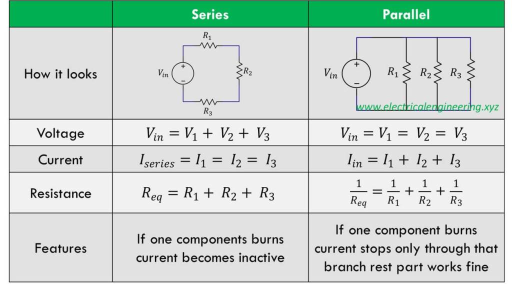
Understanding these formulas is crucial for calculating Voltage and Resistance. This mathematical choice ensures the system runs correctly and safely.
Finding Faults through Electrical Prediction
The best use of technical math is in Finding Faults. When a machine reports an electrical error (like a motor drawing too much power), the technician must use math to predict what happened.
- Calculate the Expected Value:
- Look at the schematic and use Ohm’s Law to calculate what the current draw (I) or voltage drop (V) should be for the part.
- Example: If a solenoid coil has 10 Ω of resistance on a 24 Volt DC line, the expected current is I = 24 V / 10 Ω = 2.4 A.
- Look at the schematic and use Ohm’s Law to calculate what the current draw (I) or voltage drop (V) should be for the part.
- Measure the Actual Value:
- Use a multimeter (always safely) to measure the actual voltage or current across the part.
- Find the Cause:
- Comparing your expected number to the actual measured number gives you the exact fault:
- If the actual current is much higher than 2.4 A, you have a short circuit (resistance dropped too low)
- If the actual current is zero, you have an open circuit (infinite resistance, blocking all flow).
- If the current is lower than expected but not zero, the part has excessive resistance (it’s damaged internally).
- This process transforms troubleshooting from simple trial-and-error into a logical, mathematically proven diagnosis.
- Comparing your expected number to the actual measured number gives you the exact fault:
Translating Theory into Workplace Value

Mastery of this lesson gives you critical, measurable professional skills:
- Measurement Fluency:
- Converting accurately between fractions, decimals, inches, and millimeters.
- Part Verification:
- The ability to check a part’s size against the blueprint’s tolerance (e.g., verifying a shaft diameter of 25.00 ±0.02 mm).
- Electrical Prediction:
- Using Ohm’s Law to mathematically predict what the voltage or current should be in a circuit before you measure it.
- Circuit Breakdown:
- Breaking down complex wiring diagrams into simple series and parallel sections for systematic troubleshooting.
- Quantifying Error:
- Knowing how far a measurement is from the perfect size and deciding if that distance is acceptable (within tolerance) or a total failure.
Precision measurement is a step-by-step process for confirming truth. When using tools like calipers or micrometers to check component sizes, the effective technician always uses the Discipline of the Double-Check to eliminate mistakes:
- Check the Instrument:
- Before the first use, always verify that your tool reads zero correctly and that its last calibration date is current. A measurement is only trustworthy if the tool is trustworthy.
- Measure in Three Spots:
- Never measure a critical part (like a shaft) at only one point. Measure at least three different spots and record all three readings. This ensures you catch flaws like taper (the part getting thinner) or if the part is not truly round.
- Check Against Tolerance:
- Keep the required tolerance (e.g., ±0.001 inches) in your mind while measuring. Immediately calculate how far your reading is from the ideal size. Don’t just write down the number; evaluate if the part meets the engineering requirements immediately.
Why Precision Matters
This lesson provides the quantitative language necessary for every technical task, from installing a bearing with a 0.0005 inch clearance to troubleshooting a failed solenoid. The commitment to numerical truth—through precise measurement and accurate calculation—is what separates a professional technician from a beginner. Your ability to correctly use Ohm’s Law and dimensional tolerances meets the high standards required by Advanced Manufacturing employers. In Week 4, we will take these foundational numbers and use them to understand system logic, exploring how these measurements inform the interpretation of schematics and the control flow of automated systems.